Introduction
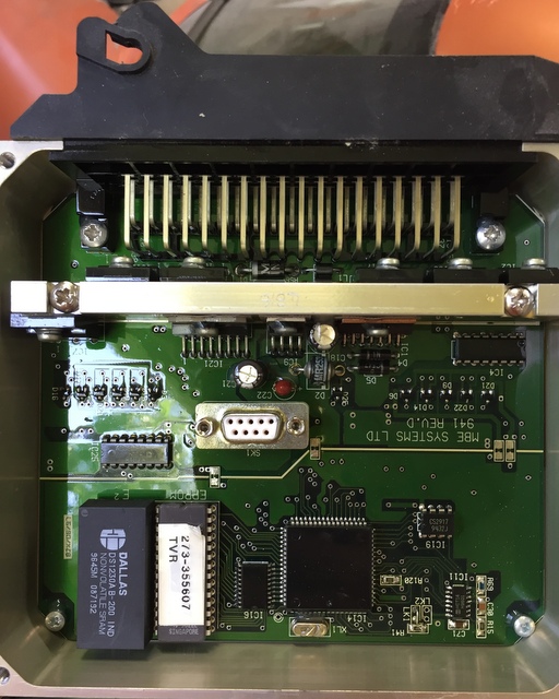
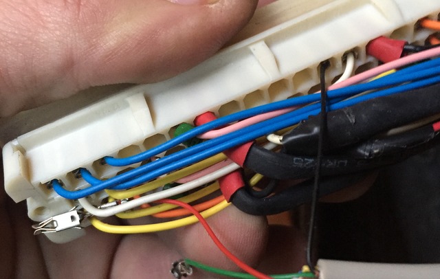
Does your ECU look like this inside ?If you've ever attempted to run diagnostics software, irrespective of which you wanted to run (RSiAJP for iOS, RS-AJP for Android, TVR Diagnostics for Windows, MBE diagnostics, etc...), you've had to remove the cover to access the serial port (white connector with 9 tiny holes in the center of the picture).
Some have made holes in the cover or the case in order to permanently fit a cable, what if there was a neater solution ?
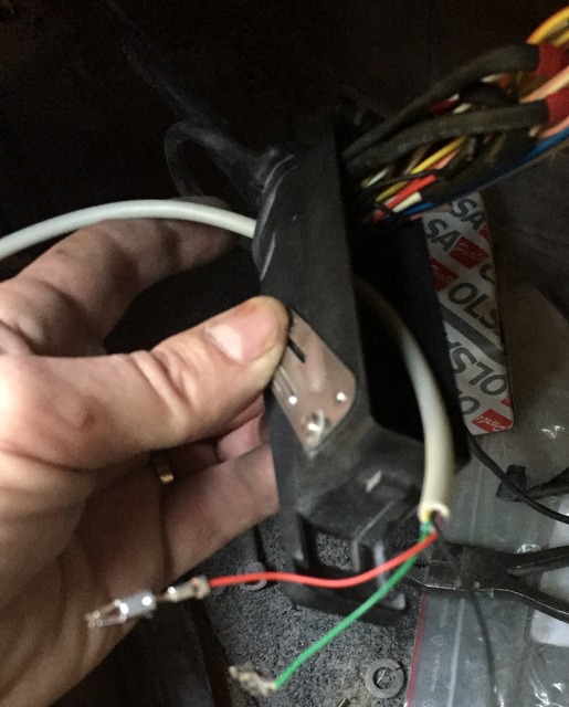
Later cars have an external 3 pin connector to which a diagnostics cable can be connected, the 3 pin connector is part of the loom. Following a little research, it appears that the relevant pins from the serial connector (pins 2, 3 and 5) are in fact connected to pins on the ECU connector itself. With a little work, it is possible to have a serial port available outside of the ECU itself, and if the cable is long enough it may even reach the cubby hole behind the gearstick or the front seat...
If any of the below looks worrying, ask an auto electrician or the person who looks after your TVR for a quote, it took me less than 1/2 hour to fit the cable, and that included taking pictures and making notes.
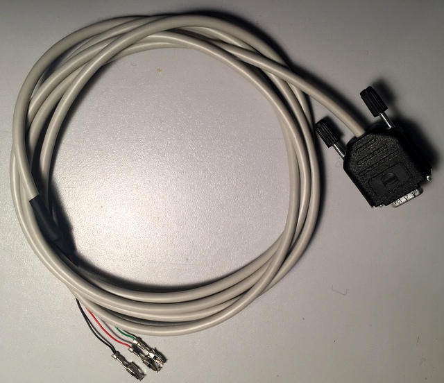
Such a cable is now available, it has been tested successfully on a 4.2 1996 Cerbera V8, below are the steps you can go through to confirm it will work on yours.
Will it work on mine ?
Theoretically yes, all ECUs were made the same, so if it works on one... but you may want to check before going ahead with the cable order.
You will need a continuity tester (multimeter) in order to check that the serial connector pins are indeed connected to the ECU connector. It is also worth checking the slots are also free on the loom connector. If you're not comfortable with this test, an auto-electrician should be able to complete it in no time at all.
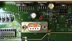
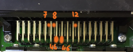
The three pins you need to test are highlighted in orange on the picture to the right. From right to left, you need to check pins 2, 3 and 5 (the top row of pins is numbered 1 to 5 from right to left).
These pins should be connected to the ECU connector as follows:
- Serial 2 to ECU pin 46
- Serial 3 to ECU pin 45
- Serial 5 to ECU pins 7, 8 and 12. Make a note of all the ones which are connected to serial 5, as it may be necessary to use one that is free on the ECU loom connector.
Note: The bottom row of ECU pins runs from 38 to 55 from left to right, and 1 to 19 for the top row, there is a middle row which we're not interested in too. If you look carefully at the printed circuit board, you'll see numbers printed near the pins (at both ends) to indicate the pin numbers.
Tips:
- The holes on the serial connector are very small and it may not be possible to inser the tip of your multimeter into them. Use a small piece of thin bare (or uninsulated at both ends) wire to fish inside the hole and connect to your meter's probe.
- The pins of the ECU connector are covered in a protective lacquer which may make initial electrical contact hit and miss, gently scratch the lacquer off with the tip of your tester's probe.
Now that you've ascertained you have continuity between the serial connector and the ECU plug, you need to check the slots in the ECU loom connector are free so that the pins from the cable can be inserted into the connector. 45 and 46 should be free, they serve no other purpose. 7, 8 and 12 however are ground pins so it's possible they are used by ground wires. On my test car, 7 was used by a large ground cable, 8 and 12 were however free.

You can see some of the slots have a connector fitted (e.g. 1, 2, 3) and others (8, 9, 10...) have nothing fitted inside them.
Check 45 and 46 are free (they should be), then check which of 7,8 and 12 are free. If 7, 8 and 12 aren't free, look for other ECU pins that are connected to serial pin 5 that may be free.
Once you have identified free slots, you're good to go with the cable.
Fitting the cable
Open the loom housing
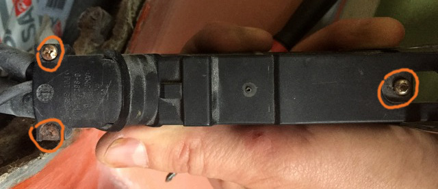
Release the loom from the ECU by pulling the metal lever away from the ECU. Then turn the housing over so you can see the top.
The screws on the left hold a strain-relief clamp over the cables entering the housing to ensure the cables aren't pulled when the connector is moved around.
The screw on the right holds the white 55 pin connector in place.
You need to remove all three.
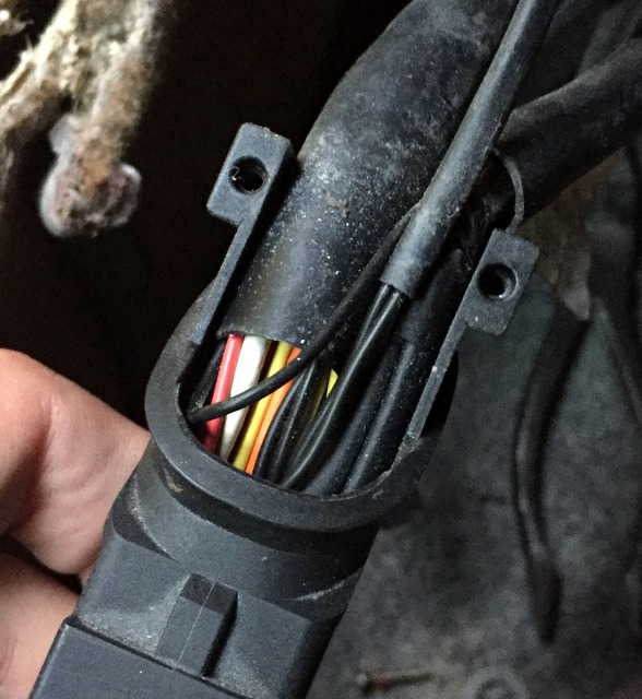
With the two strain relief screws removed, pull the plastic cover off (up and away from the housing).
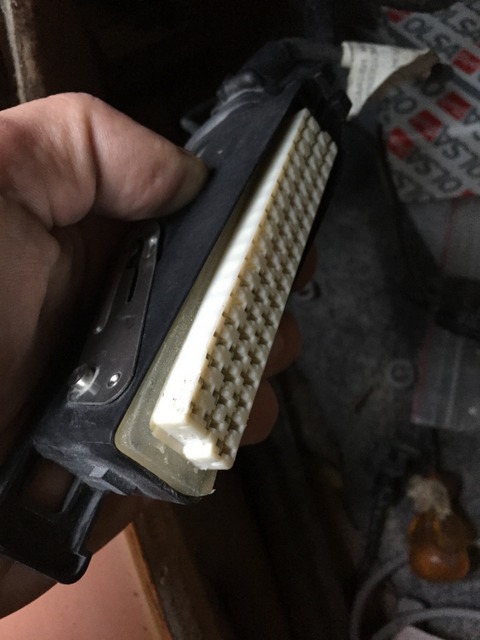
Turn the housing over and you can now free the 55 pin connector from the housing by gently prising it away with a screwdriver (avoid using pliers unless you're very gentle, you don't want to crush and break the connector !).
The connector lifts away from the housing from the end opposite the cable entry, assist it gently by pushing the cables into the housing once the far end is lifted away.
Note: There is a soft moisture and dust insulator around the connector, be careful not to damage it.
Once the connector is free, you can pull it out away from the housing, be careful to help the loom through the hole at the same time so as to not place too much strain on the cables and connector.
Threading the new cable through
Do not forget this step. Once you have pushed the pins into the 55 way connector, you'll struggle to get them out again without a special tool !!!
Now thread the new cable through the housing's hole along with the original loom, be careful not to snag the metal pins on the existing wiring and try to ensure the new cable is away from the loom and not entangled with the existing wires.
Fitting the pins into the 55 way connector
The pins are simply slotted into the corresponding hole in the connector, you'll need to push them all the way so that none of the metal part protrudes (see other pins for reference). It may be necessary to push them fully home with a small screwdriver or plastic pusher of some sort. Be careful not to damage the thin wiring as you do so.
When the pin is fully engaged, you should hear it "click" into place.
Note the orientation of the pin's slot, it must be in the same direction as other pins otherwise it will not allow the ECU connector pins through and will stop the 55 way connector from engaging fully. It is possible the pin won't engage or click if you get it wrong, but I haven't tried it to confirm.
I would recommend you fit the red and green pins first, then the black one.
The red pin goes into slot 46, the green into slot 45 and black into 7, 8, 12 (or whichever you've identified earlier).
Be sure to insert the pins into the correct slot, once inserted you'll need a special tool to remove the pin from the connector. It may be wise to thread a small wire through the slot once you have correctly identified the slot position from the front so that you know exactly which slot to insert the pin into once you turn the connector over.
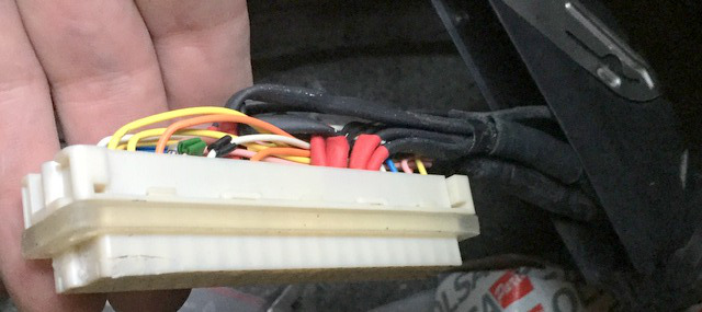
Black wire into slot 12 (note: I started with the black wire, the red and green are still loose).
Once all the pins are fully inserted, double check their location and refit the 55 way connector into its housing. The end nearest the loom entry goes first, help the cables along while you push it back into place. After the end nearest the loom entry is engaged, you can push the other end into the housing.
Refit the screw holding the 55 way connector, re-install the moisture and dust seal (it may need a little help with a screwdriver or plastic tool - be gentle) and connect the housing to the ECU.
Testing
Before switching the car on, or running any diagnostics, check the wiring is correct by running a continuity test between the ECU's serial connector pins 2, 3 and 5 with the corresponding pins on the new cable. Again you may need short lengths of thin wire in order to get a good contact with the serial connector contacts.
If all is well, you can now try your favourite ECU diagnostics application.
Completing the installation
You can now refit the strain relief cover and its two screws and refit the ECU cover for the last time.
If your adapter's blue light flashes continuously approximatively 5 seconds after power on, chances are the case is pushing the reset button at all times. The adapter will not work reliably in this condition and needs to be modified.
Note: The manufacturer confirms this to be the case with a batch of adapters (We have confirmed the problem you describe. Unfortunately we can't fix the problem until next batch of adapters. We have already notified the factory about this problem and the next batch of adapters will not have this problem. However the only solution we can offer for the current batch is to loosen the screws if the problem occurs.).
If you'd like me to perform this modification, I can order, modify and ship the modified adapter to yourself for a small charge on top of the adapter itself, alternatively you can send to adapter to me. Please email This email address is being protected from spambots. You need JavaScript enabled to view it. if you'd like to take advantage of this service.
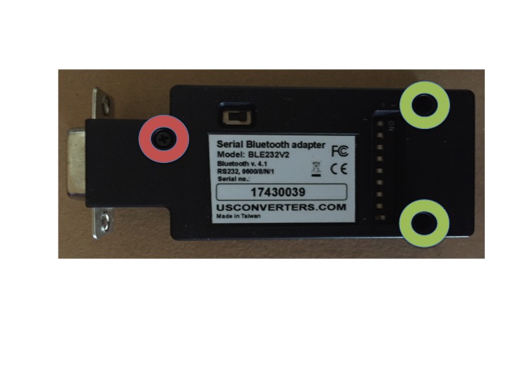
First step - loosen a screw
With the adapter powered on, loosen the screw highlighted in red in the picture below, a turn or two should be enough, you will know you have loosened it enough when the blue light stops flashing.
Second step - trim the case (optional)
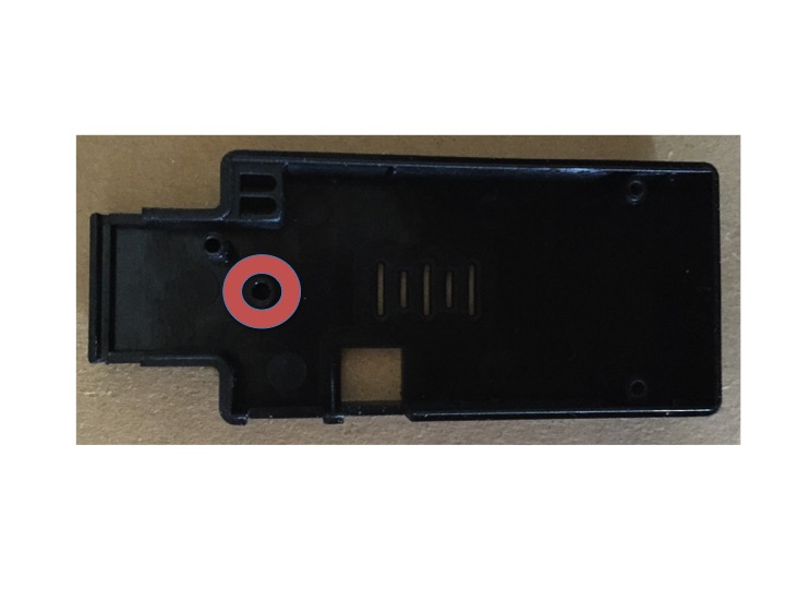
If loosening the screw wasn't sufficient, or if you want to be sure the reset switch won't be pressed at random by the case, I suggest trimming a bit of the tube highlighted in the picture below, two or three millimeters with a sharp blade should be sufficient.
Once modified, the adapter should briefly flash its blue and red lights upon power up, then red should stay on. When the app is connected to the adapter, the blue light will be on and the red light should flash.
My iPhone or iPad doesn't see the adapter
If you are looking at Settings - Bluetooth on your iPhone/iPad, you won't see the device indeed. Bluetooth Low Energy (BLE) doesn't behave like traditional bluetooth, there is no pairing with the phone, the pairing happens from the app when needed.
My adapter's blue light flashes continously and the app doesn't connect
It is likely your adapter is suffering from bad case design, see here for more details: Adapter Fix
I don't tinker with my car, do I need this ?
Even if you're not a mechanic, the app could indeed be useful to you. The MIL light has just come on but it won't tell you what's wrong, the app can and this could be useful, even to a recovery man (or woman) who most likely won't have any diagnostics capability at all. Cars with ECUs are great at hiding problems, a faulty water temperature sensor won't necessarily stop the car from working, the ECU will do its best to manage without it, however the car won't be running as well as it should, the app can tell you a sensor is faulty.
Whether you drive your car occasionally or regularly, you may not realise it is slowly loosing power, or that a throttle potentiometer isn't working but the ECU is making up for it. Why not check from time to time that all is well, even if you take the car to a specialist for a fix, knowing both throttle potentiometers are working and in sync, adaptives aren't off the scale leading to rich or lean running which isn't good for your engine, lambda sensors working as they should, any of these things could go wrong and you won't know until the next service unless you have a way of interrogating the ECU.
You could also run the app after a service to make sure all is well.
I have two (or more) TVRs, how does it work ?
You can either transfer the Bluetooth-Serial adapter from car to car, or install one in each car. The app will seamlessly connect to whichever is powered up, if both are powered up at the same time, the app should connect to the nearest one although there is no guarantee.
Where is this ECU serial connection ?
If you have never needed to connect a computer or other diagnostic tool to your ECU, you may need a few other bits and pieces. Firstly (on a Cerbera), lift the carpet in front of the passenger seat and gently pull the bottom of the panel nearest the passenger's feet towards you. I say gently because my ECU is velcroed onto the panel and the cabling to the ECU isn't very long... I don't know where the ECU is located on Tuscans, Sagaris, Tamora and T350 cars, sorry.
Once you have done this, you should find an anodised box, roughly five inches square and 1.5 inches thick, this is your ECU. Next you need to identify if you have the later ECUs with the three pin diagnostics cable, or the earlier one with the serial connector inside the ECU.
3 Pin diagnostics (Usually found on Speed 6 cars, however my V8 has this type of connection)
Follow the wiring from the large connector at the ECU and look for three wires floating about with a black three pin connector on the end (picture here: https://www.pistonheads.com/gassing/topic.asp?t=1286401). If you have this, you'll need to make or order a serial cable.
To make it: https://www.pistonheads.com/gassing/topic.asp?t=1286401
To order it (data lead from TVR Parts - there may be other suppliers): https://tvr-parts.com/tvr-parts/part-details/tvr-rp004/data-lead
Onboard Serial Connection
Some ECUs have a serial connector soldered onto the ECU's circuit board, if you've not found the 3 pin connector above, you'll now have to open your ECU to find this connector. There are several discussions on PistonHeads on this topic, some have made a hole in the top of the ECU cover in order to gain permanent access to the connector for example.
So, unless you are looking for a longer term solution (cable permanently in place), you can simply plug the Serial-Bluetooth adapter onto the ECU's serial port and power the adapter up through USB or otherwise. For a longer term solution, it would be best fit a serial cable and the adapter at the end of that cable. The cable you would need is http://www.maplin.co.uk/p/serial-rs232-9-pin-male-to-9-pin-female-3m-web-only-l67bt or https://tvr-parts.com/tvr-parts/part-details/tvr-l67bt/data-lead if you want the genuine (and more expensive) article.
I have two (or more) iOS devices, do I need to purchase the app for each ?
No, so long as they share the same apple id, once you have purchased the app, you can install it on any number of devices. The app is also compatible with iPhone and iPad, so unlike some apps there is no need to purchase it twice should you want to run it on an iPhone and iPad. The only requirement is that the iOS devices have at least iOS 10.3 installed.
Hi, my name's Greg and it feels like I've been writing software for ever ! I started at the tender age of 10 - living in France - and my parents decided to enroll me on an evening course full of adults !
Making my debuts on ZX-81 and Tandy TRS80, I progressed onto lesser known computers such as the Commodore +4 and Amstrad PCW8256 (a word processing machine !). By the age of 14, I had written a maths graphing program for the 8256 which was published in a magazine in the days where you copied magazine pages' worth of code because you couldn't download from the internet ! My parents and grandparents were very proud, less impressed by the huge stereo I purchased with the proceeds of the publication !
I eventually made my way into university where I got a degree in electronics, robotics and computer programming. I followed this degree by moving to the UK where I first tested hardware (300M Hard Drive and 40Mhz CPUs were the rage then !) and slowly progressed through the ranks until I started working for a small UK company as a software developper, first working on small one-man projects and then moving onto their flagship product.
I stayed with the same company for nearly 20 years, growing through the ranks and through two acquisitions ended up at Cisco where I was a Principle Engineer, responsible for the architecture, strategy and evolution of three pieces of software which were used by major telecommunications companies throughout the world.
I moved back to France in 2015 for personal reasons and not long after that found myself staring at a redundancy letter which was the prompt for me to leave the rat race and look forward to a more peaceful life in the French countryside. I am now renovating and renting two gites (holiday homes) and in my spare time, let my many passions (including cars and software development) run riot.
In the interest of transparency below is a list of issues known to exist in the currently shipping version of RSiAJP and/or RSiAJP Lite, we are working to correct these as soon as possible.


