")
")
Uncategorised
Introduction
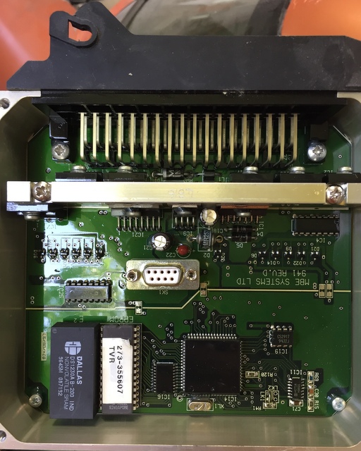
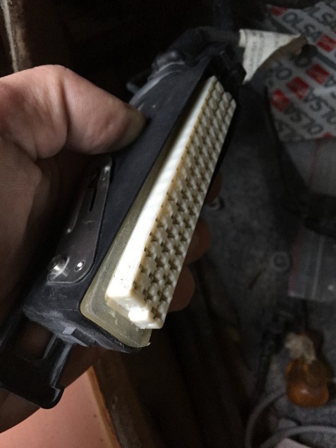
Does your ECU look like this inside ?If you've ever attempted to run diagnostics software, irrespective of which you wanted to run (RSiAJP for iOS, RS-AJP for Android, TVR Diagnostics for Windows, MBE diagnostics, etc...), you've had to remove the cover to access the serial port (white connector with 9 tiny holes in the center of the picture).
Some have made holes in the cover or the case in order to permanently fit a cable, what if there was a neater solution ?
Later cars have an external 3 pin connector to which a diagnostics cable can be connected, the 3 pin connector is part of the loom. Following a little research, it appears that the relevant pins from the serial connector (pins 2, 3 and 5) are in fact connected to pins on the ECU connector itself. With a little work, it is possible to have a serial port available outside of the ECU itself, and if the cable is long enough it may even reach the cubby hole behind the gearstick or the front seat...
If any of the below looks worrying, ask an auto electrician or the person who looks after your TVR for a quote, it took me less than 1/2 hour to fit the cable, and that included taking pictures and making notes.
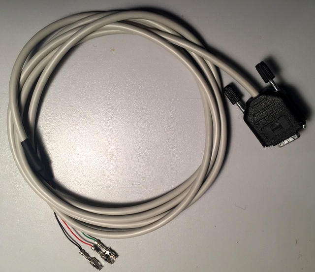
Such a cable is now available, it has been tested successfully on a 4.2 1996 Cerbera V8, below are the steps you can go through to confirm it will work on yours.
Will it work on mine ?
Theoretically yes, all ECUs were made the same, so if it works on one... but you may want to check before going ahead with the cable order. 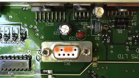
You will need a continuity tester (multimeter) in order to check that the serial connector pins are indeed connected to the ECU connector. It is also worth checking the slots are also free on the loom connector. If you're not comfortable with this test, an auto-electrician should be able to complete it in no time at all.
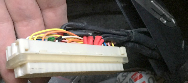
The three pins you need to test are highlighted in orange on the picture to the right. From right to left, you need to check pins 2, 3 and 5 (the top row of pins is numbered 1 to 5 from right to left).
These pins should be connected to the ECU connector as follows:
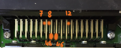
- Serial 2 to ECU pin 46
- Serial 3 to ECU pin 45
- Serial 5 to ECU pins 7, 8 and 12. Make a note of all the ones which are connected to serial 5, as it may be necessary to use one that is free on the ECU loom connector.
Note: The bottom row of ECU pins runs from 38 to 55 from left to right, and 1 to 19 for the top row, there is a middle row which we're not interested in too. If you look carefully at the printed circuit board, you'll see numbers printed near the pins (at both ends) to indicate the pin numbers.
Tips:
- The holes on the serial connector are very small and it may not be possible to inser the tip of your multimeter into them. Use a small piece of thin bare (or uninsulated at both ends) wire to fish inside the hole and connect to your meter's probe.
- The pins of the ECU connector are covered in a protective lacquer which may make initial electrical contact hit and miss, gently scratch the lacquer off with the tip of your tester's probe.
Now that you've ascertained you have continuity between the serial connector and the ECU plug, you need to check the slots in the ECU loom connector are free so that the pins from the cable can be inserted into the connector. 45 and 46 should be free, they serve no other purpose. 7, 8 and 12 however are ground pins so it's possible they are used by ground wires. On my test car, 7 was used by a large ground cable, 8 and 12 were however free.
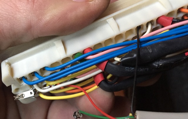
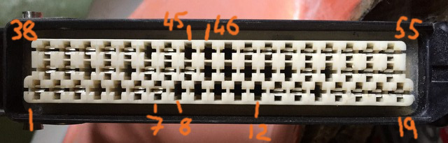 The slots on the loom connector are numbered as per the image to the right, note that the bottom row is longer than the other two.
You can see some of the slots have a connector fitted (e.g. 1, 2, 3) and others (8, 9, 10...) have nothing fitted inside them.
Check 45 and 46 are free (they should be), then check which of 7,8 and 12 are free. If 7, 8 and 12 aren't free, look for other ECU pins that are connected to serial pin 5 that may be free.
Once you have identified free slots, you're good to go with the cable.
Fitting the cable
Open the loom housing
Release the loom from the ECU by pulling the metal lever away from the ECU. Then turn the housing over so you can see the top.
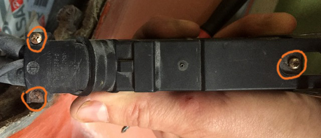
The screws on the left hold a strain-relief clamp over the cables entering the housing to ensure the cables aren't pulled when the connector is moved around.
The screw on the right holds the white 55 pin connector in place.
You need to remove all three.
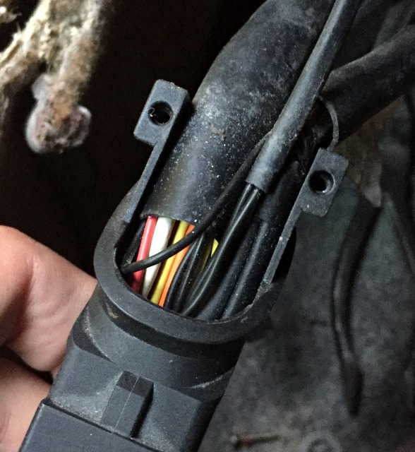
With the two strain relief screws removed, pull the plastic cover off (up and away from the housing).
Turn the housing over and you can now free the 55 pin connector from the housing by gently prising it away with a screwdriver (avoid using pliers unless you're very gentle, you don't want to crush and break the connector !).
The connector lifts away from the housing from the end opposite the cable entry, assist it gently by pushing the cables into the housing once the far end is lifted away.
Note: There is a soft moisture and dust insulator around the connector, be careful not to damage it.
Once the connector is free, you can pull it out away from the housing, be careful to help the loom through the hole at the same time so as to not place too much strain on the cables and connector.
Threading the new cable through
Do not forget this step. Once you have pushed the pins into the 55 way connector, you'll struggle to get them out again without a special tool !!!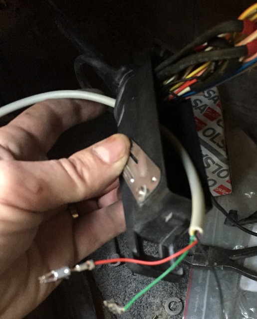
Now thread the new cable through the housing's hole along with the original loom, be careful not to snag the metal pins on the existing wiring and try to ensure the new cable is away from the loom and not entangled with the existing wires.
Fitting the pins into the 55 way connector
The pins are simply slotted into the corresponding hole in the connector, you'll need to push them all the way so that none of the metal part protrudes (see other pins for reference). It may be necessary to push them fully home with a small screwdriver or plastic pusher of some sort. Be careful not to damage the thin wiring as you do so.
When the pin is fully engaged, you should hear it "click" into place.
Note the orientation of the pin's slot, it must be in the same direction as other pins otherwise it will not allow the ECU connector pins through and will stop the 55 way connector from engaging fully. It is possible the pin won't engage or click if you get it wrong, but I haven't tried it to confirm.

I would recommend you fit the red and green pins first, then the black one.
The red pin goes into slot 46, the green into slot 45 and black into 7, 8, 12 (or whichever you've identified earlier).
Be sure to insert the pins into the correct slot, once inserted you'll need a special tool to remove the pin from the connector. It may be wise to thread a small wire through the slot once you have correctly identified the slot position from the front so that you know exactly which slot to insert the pin into once you turn the connector over.
Black wire into slot 12 (note: I started with the black wire, the red and green are still loose).
Once all the pins are fully inserted, double check their location and refit the 55 way connector into its housing. The end nearest the loom entry goes first, help the cables along while you push it back into place. After the end nearest the loom entry is engaged, you can push the other end into the housing.
Refit the screw holding the 55 way connector, re-install the moisture and dust seal (it may need a little help with a screwdriver or plastic tool - be gentle) and connect the housing to the ECU.
Testing
Before switching the car on, or running any diagnostics, check the wiring is correct by running a continuity test between the ECU's serial connector pins 2, 3 and 5 with the corresponding pins on the new cable. Again you may need short lengths of thin wire in order to get a good contact with the serial connector contacts.
If all is well, you can now try your favourite ECU diagnostics application.
Completing the installation
You can now refit the strain relief cover and its two screws and refit the ECU cover for the last time.
Si la LED de votre adapteur clignote de façon permanente environ 5 secondes après avoir alimenté celui-ci, il est probable que le boitier de l'adaptateur pousse le bouton "reset" en permanence. Il est alors nécessaire de le modifier afin qu'il fonctionne correctement.
Note: Le fabricant confirm que ceci est en effet un problème avec certains adaptateurs (We have confirmed the problem you describe. Unfortunately we can't fix the problem until next batch of adapters. We have already notified the factory about this problem and the next batch of adapters will not have this problem. However the only solution we can offer for the current batch is to loosen the screws if the problem occurs.).
Si vous voulez que je fasse la modification pour vous, je peux commander, modifier et vous envoyer un adaptateur testé, ou vous pouvez m'envoyer votre adaptateur. Envoyez un mail à Cette adresse e-mail est protégée contre les robots spammeurs. Vous devez activer le JavaScript pour la visualiser. si vous êtes intéressé(e).
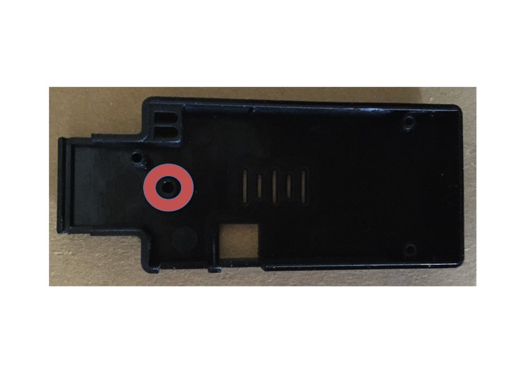
Première étape - dévisser une vis
Pendant que l'adaptateur est alimenté, dévissez la vis identifiée en rouge ci-dessous. Un tour ou deux devrait suffire, vous saurez que vous avez dévissé suffisamment lorsque la led blue ne clignote plus.
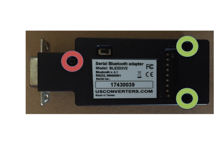
Deuxième étape - modifier le capot
Si le dévissage n'était pas suffisant, ou que vous voulez vous assurer que le bouton "reset" ne sera pas actionné de façon intempestive, je suggère que le tube qui se trouve au dessus de l'interrupteur (en rouge ci-dessous) soit réduit en hauteur. Il suffit d'enlever 2 ou 3 millimètre au cutter.
Once modified, the adapter should briefly flash its blue and red lights upon power up, then red should stay on. When the app is connected to the adapter, the blue light will be on and the red light should flash.
Mon iPhone ou iPad ne voit pas l'adaptateur
Si vous êtes dans Paramètres - Bluetooth, il est normal de ne pas voir l'adaptateur. En effet, Bluetooth Low Energy (BLE) ne fonctionne pas comme le Bluetooth traditionnel, il n'y a pas d'appairage préalable, tout se fait automatiquement depuis l'appli.
La LED bleue de mon adaptateur clignote et l'appli ne se connecte pas
Il est probable que votre adaptateur aie un problème de capot, voir ici pour plus d'information: Modification adaptateur
Je ne suis pas mécano, ai-je besoin de l'appli ?
Même si vous n'êtes pas mécanicien, cette appli peut vous être utile. L'indicateur MIL (et le buzzer) vient de s'allumer mais ne vous dis pas ce qui ne plaît pas au calculateur, l'appli vous le dira et ceci pourrait être utile à un dépanneur qui lui n'aura probablement pas les outils de diagnostic nécessaires. Les voitures équipées d'un calculateur sont aussi aptes à cacher une multitude de problème, ceci par exemple en substituant une valeur standard pour un capteur défaillant. L'auto continuera à fonctionner, mais pas forcément de manière optimales. L'appli vous dira si un capteur n'est plus (ou mal) reconnu par le calculateur.
Que vous conduisiez votre voiture régulièrement ou pas, vous ne vous rendrez pas forcément compte qu'elle perd de la puissance, ou qu'un capteur de papillon ne fonctionne plus mais que le calculateur se débrouille sans. Pourquoi ne pas vérifier de temps en temps que tout est en ordre, même si vous faites faire les travaux de réparation par un spécialiste, savoir que les capteurs de papillons sont linéaire et synchronisés, que les sondes lambda fonctionnent correctement, que les adaptives sont dans les normes et que votre mélange n'est ni trop riche ni trop pauvre ce qui pourrait être néfaste à la bonne santé du moteur est indispensable. Sans l'appli vous ne saurez qu'à l'occasion d'une révision, et cela pourrait être 11 mois de roulage sans savoir qu'un problème existe !
Vous pouvez aussi utiliser l'application pour vous assurer que le professionnel en question a bien fait son travail.
J'ai deux (ou plus) TVR, comment ça marche ?
Vous pouvez soit transférer l'adaptateur d'une voiture à l'autre, ou installer un adaptateur dans chaque. L'appli se connectera automatiquement à celui qui est sous tension, si les deux sont sous en même temps, elle se connectera au plus proche, bien que cela ne puisse être garanti.
Où est cette connexion série ?
Si vous n'avez jamais connecté un ordinateur ou autre outil de diagnostic, il vous faudra peut-être un câble supplémentaire. Tout d'abord (sur une Cerbera), soulevez la moquette devant le siège passager, puis tirez doucement sur le bas du panneau près des pieds du passager. Doucement parce-que mon calculateur est attaché avec du velcro et il serait dommage d'endommager le faisceau qui n'est pas très long. Je ne sais pas où se trouve le calculateur sur les Tuscan, Sagaris, Tamora et T350, désolé.
Une fois ceci fait, vous verrez une boite en métal, approximativement 15cm de coté et 3cm d'épaisseur, ceci est votre calculateur. Il faut maintenant déterminer si vous avez le calculateur avec le connecteur de diagnostic ou pas.
Connecteur diagnostic (Généralement trouvé sur les S6, mais ma Cerbera V8 en a un !)
Suivez le faisceau depuis le gros connecteur du calculateur et cherchez un connecteur à 3 prises (photo ici: https://www.pistonheads.com/gassing/topic.asp?t=1286401). Si vous trouvez ce connecteur, il vous faudra commander le cable nécessaire, ou le fabriquer.
Pour le fabriquer: https://www.pistonheads.com/gassing/topic.asp?t=1286401
Pour l'acheter (data lead de TVR Parts - d'autres fournisseurs existent): https://tvr-parts.com/tvr-parts/part-details/tvr-rp004/data-lead
Connecteur Série sur le calculateur
Certains calculateurs ont le connecteur série soudé sur leur circuit imprimé, si vous n'avez pas trouvé le connecteur à trois broches ci-dessus, il vous faudra ouvrir le capot du calculateur pour trouver le connecteur DB9 (9 broches). Il y a plusieurs discussions à ce sujet sur pistonheads à ce sujet, certains on percé un trou dans le capot du calculateur pour y laisser passer un câble de façon permanente. N'hésitez pas à me demander si vous avez besoin d'aide.
A moins de vouloir une solution permanente avec un câble fixé en place, vous pouvez tout simplement connecter l'adaptateur Bluetooth-Série au connecteur du calculateur et alimenter l'adaptateur soit par câble usb ou directement. Pour une solution long terme, il serait mieux de trouver un câble série male-femelle plûtot que de laisser l'adaptateur connecté car ceci pourrait être mécaniquement mauvais pour la longévité du circuit imprimé (vibrations, etc...). Le cable dont vous aurez besoin se trouve chez TVR Parts https://tvr-parts.com/tvr-parts/part-details/tvr-l67bt/data-lead, mais le même câble est disponible ailleurs et moins cher.
J'ai deux (ou plus) iPhones et/ou iPads, dois-je acheter l'appli plusieurs fois ?
Non, tant qu'ils utilisent tous le même identifiant Apple (Apple ID), une fois l'appli achetée vous pouvez l'installer sur autant d'appareils que vous le voulez. Il n'y a pas de différence non plus entre les versions iPad et iPhone, ce sont les mêmes donc pas besoin d'acheter deux applis comme certains vous le demandent. Il est cela dit nécessaire que chaque appareil aie la version 10.3 d'iOS au minimum.
Salut, je m'appelle Greg et j'ai l'impression d'avoir écrit du logiciel depuis toujours ! J'ai commencé á l'age de 10 ans et mes parents on décidé de m'inscrire à un cours d'informatique du soir plein d'adultes !
J'ai commencé sur un ordinateur ZX-81 et Tandy TRS80 (aussi Thomson TO7-70), pour ensuite passer sur des ordinateurs moins connus tels que le Commodore +4 et l'Amstrad PCW8256 (un ordinateur de traitement de texte !). A l'age de 14 ans, j'ai écrit un programme de tracé de fonctions mathématiques pour le 8256 qui a été publié dans un magazine, ceci au temps où l'on recopiait des programmes depuis les magazines à la main car on ne pouvait pas les télécharger par internet ! Mes parents et grands-parents étaient impressionnés, moins par la chaine stéréo énorme que je me suis acheté avec les royalties !
J'ai finalement obtenu un diplôme en électronique, automatismes et programmation, que j'ai suivi par un déplacement en Angleterre où mon premier boulot était de tester du matériel informatique (un disque dur de 300Meg et un processeur de 40Mhz étaient à l'époque le top du top). J'ai ensuite rejoint une petite companie qui spécialisait dans le développement logiciel, travaillant au début sur des petits projets, puis ensuite sur leur produit phare.
Je suis resté avec le même employeur presque 20 ans, j'ai vécu deux acquisitions et ai fini cadre supérieur chez Cisco où j'étais responsable de l'architecture, stratégie et évolution de trois produits qui étaient utilisés par des opérateurs télécom à travers le monde.
Je suis revenu en France en 2015 pour des raisons personnelles et peu de temps après me suis retrouvé face à un licenciement. N'ayant plus envie de vivre pour travailler, j'ai décidé de chercher un vie plus simple et plus modeste à la campagne. Je suis en train de rénover deux gîtes et le temps libre qu'il me reste me permet de me dévouer à mes passions, qui entre-autres incluent l'automobile et le développement logiciel.
In the interest of transparency below is a list of issues known to exist in the currently shipping version of RSiAJP and/or RSiAJP Lite, we are working to correct these as soon as possible.
- Vous êtes ici :
-
Accueil

- Uncategorised