Introduction
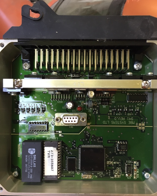
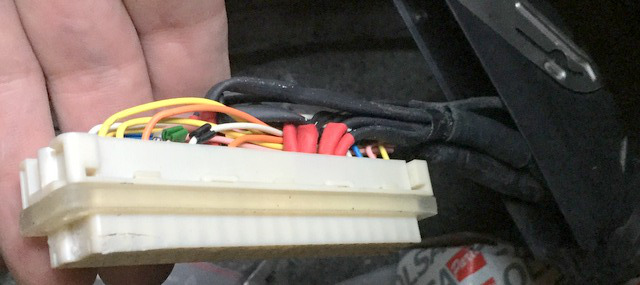
Does your ECU look like this inside ?If you've ever attempted to run diagnostics software, irrespective of which you wanted to run (RSiAJP for iOS, RS-AJP for Android, TVR Diagnostics for Windows, MBE diagnostics, etc...), you've had to remove the cover to access the serial port (white connector with 9 tiny holes in the center of the picture).
Some have made holes in the cover or the case in order to permanently fit a cable, what if there was a neater solution ?
Later cars have an external 3 pin connector to which a diagnostics cable can be connected, the 3 pin connector is part of the loom. Following a little research, it appears that the relevant pins from the serial connector (pins 2, 3 and 5) are in fact connected to pins on the ECU connector itself. With a little work, it is possible to have a serial port available outside of the ECU itself, and if the cable is long enough it may even reach the cubby hole behind the gearstick or the front seat...
If any of the below looks worrying, ask an auto electrician or the person who looks after your TVR for a quote, it took me less than 1/2 hour to fit the cable, and that included taking pictures and making notes.
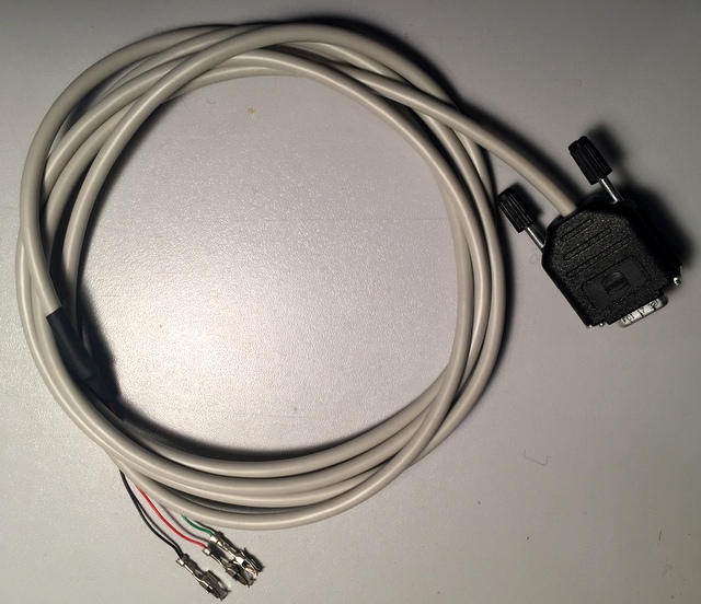
Such a cable is now available, it has been tested successfully on a 4.2 1996 Cerbera V8, below are the steps you can go through to confirm it will work on yours.
Will it work on mine ?
Theoretically yes, all ECUs were made the same, so if it works on one... but you may want to check before going ahead with the cable order. 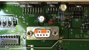
You will need a continuity tester (multimeter) in order to check that the serial connector pins are indeed connected to the ECU connector. It is also worth checking the slots are also free on the loom connector. If you're not comfortable with this test, an auto-electrician should be able to complete it in no time at all.
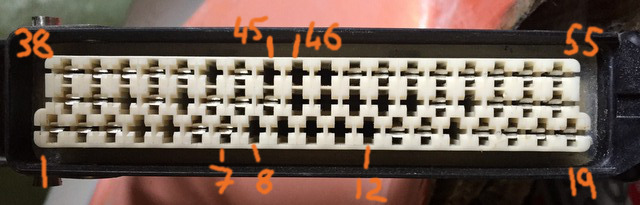
The three pins you need to test are highlighted in orange on the picture to the right. From right to left, you need to check pins 2, 3 and 5 (the top row of pins is numbered 1 to 5 from right to left).
These pins should be connected to the ECU connector as follows:
- Serial 2 to ECU pin 46
- Serial 3 to ECU pin 45
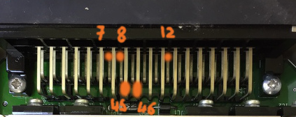
- Serial 5 to ECU pins 7, 8 and 12. Make a note of all the ones which are connected to serial 5, as it may be necessary to use one that is free on the ECU loom connector.
Note: The bottom row of ECU pins runs from 38 to 55 from left to right, and 1 to 19 for the top row, there is a middle row which we're not interested in too. If you look carefully at the printed circuit board, you'll see numbers printed near the pins (at both ends) to indicate the pin numbers.
Tips:
- The holes on the serial connector are very small and it may not be possible to inser the tip of your multimeter into them. Use a small piece of thin bare (or uninsulated at both ends) wire to fish inside the hole and connect to your meter's probe.
- The pins of the ECU connector are covered in a protective lacquer which may make initial electrical contact hit and miss, gently scratch the lacquer off with the tip of your tester's probe.
Now that you've ascertained you have continuity between the serial connector and the ECU plug, you need to check the slots in the ECU loom connector are free so that the pins from the cable can be inserted into the connector. 45 and 46 should be free, they serve no other purpose. 7, 8 and 12 however are ground pins so it's possible they are used by ground wires. On my test car, 7 was used by a large ground cable, 8 and 12 were however free.
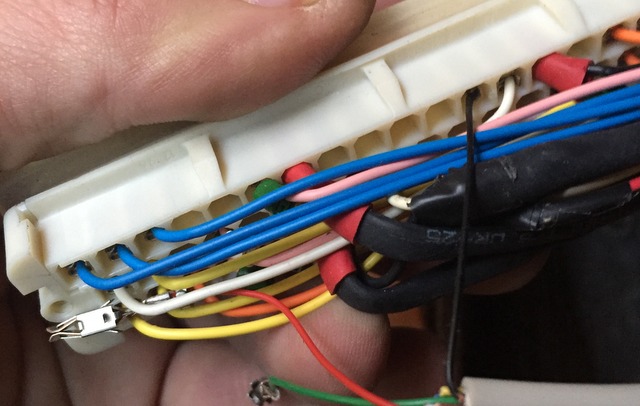
 The slots on the loom connector are numbered as per the image to the right, note that the bottom row is longer than the other two.
You can see some of the slots have a connector fitted (e.g. 1, 2, 3) and others (8, 9, 10...) have nothing fitted inside them.
Check 45 and 46 are free (they should be), then check which of 7,8 and 12 are free. If 7, 8 and 12 aren't free, look for other ECU pins that are connected to serial pin 5 that may be free.
Once you have identified free slots, you're good to go with the cable.
Fitting the cable
Open the loom housing
Release the loom from the ECU by pulling the metal lever away from the ECU. Then turn the housing over so you can see the top.
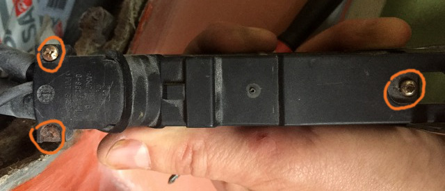
The screws on the left hold a strain-relief clamp over the cables entering the housing to ensure the cables aren't pulled when the connector is moved around.
The screw on the right holds the white 55 pin connector in place.
You need to remove all three.
With the two strain relief screws removed, pull the plastic cover off (up and away from the housing).
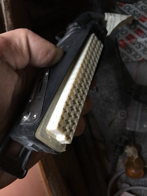
Turn the housing over and you can now free the 55 pin connector from the housing by gently prising it away with a screwdriver (avoid using pliers unless you're very gentle, you don't want to crush and break the connector !).
The connector lifts away from the housing from the end opposite the cable entry, assist it gently by pushing the cables into the housing once the far end is lifted away.
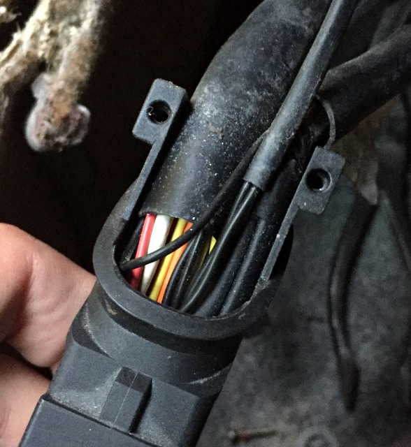
Note: There is a soft moisture and dust insulator around the connector, be careful not to damage it.
Once the connector is free, you can pull it out away from the housing, be careful to help the loom through the hole at the same time so as to not place too much strain on the cables and connector.
Threading the new cable through
Do not forget this step. Once you have pushed the pins into the 55 way connector, you'll struggle to get them out again without a special tool !!!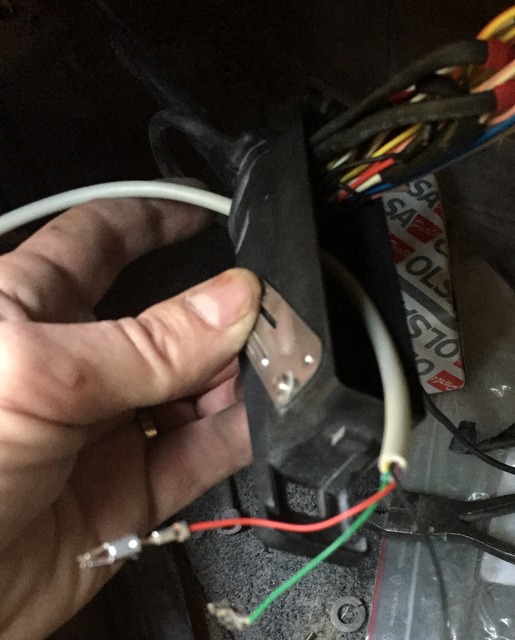
Now thread the new cable through the housing's hole along with the original loom, be careful not to snag the metal pins on the existing wiring and try to ensure the new cable is away from the loom and not entangled with the existing wires.
Fitting the pins into the 55 way connector
The pins are simply slotted into the corresponding hole in the connector, you'll need to push them all the way so that none of the metal part protrudes (see other pins for reference). It may be necessary to push them fully home with a small screwdriver or plastic pusher of some sort. Be careful not to damage the thin wiring as you do so.
When the pin is fully engaged, you should hear it "click" into place.
Note the orientation of the pin's slot, it must be in the same direction as other pins otherwise it will not allow the ECU connector pins through and will stop the 55 way connector from engaging fully. It is possible the pin won't engage or click if you get it wrong, but I haven't tried it to confirm.

I would recommend you fit the red and green pins first, then the black one.
The red pin goes into slot 46, the green into slot 45 and black into 7, 8, 12 (or whichever you've identified earlier).
Be sure to insert the pins into the correct slot, once inserted you'll need a special tool to remove the pin from the connector. It may be wise to thread a small wire through the slot once you have correctly identified the slot position from the front so that you know exactly which slot to insert the pin into once you turn the connector over.
Black wire into slot 12 (note: I started with the black wire, the red and green are still loose).
Once all the pins are fully inserted, double check their location and refit the 55 way connector into its housing. The end nearest the loom entry goes first, help the cables along while you push it back into place. After the end nearest the loom entry is engaged, you can push the other end into the housing.
Refit the screw holding the 55 way connector, re-install the moisture and dust seal (it may need a little help with a screwdriver or plastic tool - be gentle) and connect the housing to the ECU.
Testing
Before switching the car on, or running any diagnostics, check the wiring is correct by running a continuity test between the ECU's serial connector pins 2, 3 and 5 with the corresponding pins on the new cable. Again you may need short lengths of thin wire in order to get a good contact with the serial connector contacts.
If all is well, you can now try your favourite ECU diagnostics application.
Completing the installation
You can now refit the strain relief cover and its two screws and refit the ECU cover for the last time.